Last week, our 1st science students had their first laboratory session on electrical circuits. They haven’t met electricity in lectures yet, so I spent some time explaining the concepts of current and voltage.
In essence, current is the flow of electric charge around a circuit (measured in amps) while voltage is the energy that drives the current (and is measured in volts). I find it helpful to think of the two in terms of cause and effect; a current will only flow in the circuit if a voltage is applied. In simple circuits, this energy is supplied in the form of a DC battery (or voltage source) that drives the current through some device (or resistor) in the circuit.

The lamp (or resistor) lights as the current goes through it, completing the circuit
You might expect that there is a simple relation between voltage and current, and sure enough, the German scientist Georg Ohm discovered that, for many materials, there is a linear relationship between the two. Ohm’s law states that the current I passing through a material connected to a voltage V is given by the simple equation I = V/R. Here, 1/R is the constant of proportionality and is called electrical resistance and you can see why from the equation: a material with a very large value of R will pass almost no current (bad conductor), while a material with very small R will yield a large current for the same voltage (good conductor). So the term has exactly the same meaning as it has in ordinary speech, e.g. the French resistance. Resistance is measured in volts per amp, also known as Ohms (Ω).
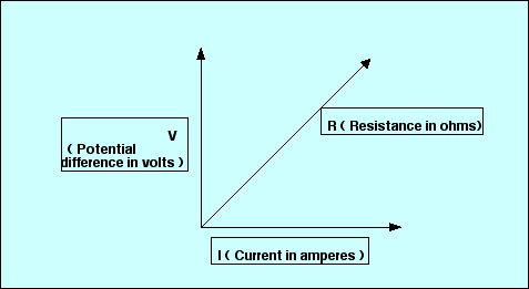
Many materials have a linear relation between voltage and current – the slope of the graph is the material’s resistance
In the experiment, the students apply a series of voltages to an unknown resistance in a circuit, and record the corresponding currents. A plot of voltage versus current then allows them to verify the linearity of the relation and the resistance is estimated from the slope of the line. (Strictly speaking, one should really put the voltage on the x-axis as it is the independent variable, but the calculation is simpler if the voltage is on the y-axis).
Measuring current and voltage
All of the above is fine in principle. Yet novices find the measurements quite difficult in practice. They have problems connecting the circuit because they get confused between measuring the current that flows through a device, and the voltage across it. It’s crucial to understand the difference between the two, and I suspect the modern multimeter adds to the confusion.

The ammeter reads the current running through the resistor while the voltmeter reads the voltage across it. A plot of voltage vs current gives a measurement of the resistance
When I was a student, the current was measured by passing the current through an ammeter (marked A in the diagram), an analog device with a nice big dial calibrated in amps or milliamps. The voltage across the resistor was measured by connecting a different instrument, the voltmeter, across the terminals of the resistor; this voltmeter was a separate meter with a dial calibrated in volts (marked V in the diagram). So an ammeter was always connected in series with the resistor/device, while the voltmeter was always connected across it (in parallel).


Current is measured by passing it through the ammeter (L) while voltage is measured by connecting across the voltmeter (R)
Nowadays, identical instruments are used for both; to measure current, one passes the current through the terminals marked ‘current’ of a multimeter, and the main dial on the meter is switched to the amp scale. To measure voltage, one connects the ends of the resistor across the terminals marked ‘voltage’ on an identical multimeter, and the dial is switched to volts. It sounds simple, but it’s easy to connect to the wrong terminals, getting no readings or blowing the fuse in the meter. More subtly, I think the clever circuity inside the multimeter hides the fact that current goes through while voltage drops across. All in all, I suspect students would understand circuits better if we went back to separate instruments for measuring current and voltage….

The mysterious multimeter. To measure current, leads are connected to the sockets marked ‘common’ and ‘amps’; to measure voltage, one connects to the sockets marked ‘common’ and ‘voltage’.
Notes
1. If a 12-V voltage is applied across a resistor of 15 kΩ, what current flows in the circuit? How many electrons per second does this current represent? (Ans: 0.8 mA, 5.0 x 10¹⁵ electrons)
2. What happens to the current if one end of the resistor accidentally touches the other? (Ans: the circuit resistance drops almost to zero and the current becomes very large – don’t try this in the lab!)
3. Ohm’s law is a misnomer – it is not a universal law of nature but simply a property of some materials (many materials have a nonlinear response to voltage, including your cat).
4. It might seem from Ohm’s law that a material with zero resistance can give infinite current! No such materials are known; the relation is simply not valid for these materials. However, some materials have extremely low resistance at very low temperatures, known as superconductors. A good application of superconductivity can be found at the Large Hadron Collider, where protons are guided around the ring by magnets made of superconducting material: this reduces power consumption enormously but the snag is that the entire accelerator has to be kept at extremely low temperatures during the experiments.

I like science although I don’t like math
Nobody cares.
fuuuaar
think youre good??